
Technical Deep Dive · Facade Engineering
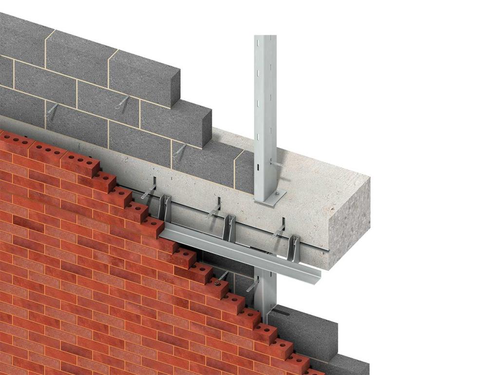
The most important stainless steel in a stone or brick facade may be the part no one sees. Hidden ties, support angles, brackets and anchors connect the masonry skin to the structural frame while tolerating movement, managing moisture and remaining traceable after close-up. This guide shows how to specify that package: map the load path, separate fixed and sliding functions, coordinate interfaces, control tolerances and record concealed work.
Why concealed support deserves its own specification
Stone and brick are the visible facade, not the whole system. Behind them may be a cavity, backing wall, frame, flashing, support angle, wall tie, clip, bracket or post-installed anchor. Each has a different function: restraint, bearing, force transfer or water control. Calling them all “fixings” hides the decisions that make the assembly work.
The Nickel Institute’s architecture and construction overview includes support and connection uses for stainless steel. A detailed ASSDA case study of the Phoenix Central Park Gallery shows why: complex brick geometry was connected to the structural steel and concrete frame through bespoke ties, support angles and custom solutions. Its quantities belong to that project; the transferable lesson is to coordinate the hidden package before close-up.
Start with the load path, not the anchor catalogue
Begin with a section and trace each action from the visible skin back to the building: stone or brick, restraint or bearing component, bracket or support angle, anchor or channel, then backing wall or structural frame. The sequence depends on whether the assembly is a veneer, cavity wall, stone rainscreen, brick screen or restoration system.
For every connection, identify what it carries and what it releases. Dead, wind, seismic, thermal, deflection and tolerance effects should not be collapsed into one generic capacity line. The responsible structural and facade designers must establish design actions, substrate condition, test method and code route. This avoids selecting an anchor by diameter or catalogue appearance before deciding which interface is fixed, which slides, where movement is collected and how the load reaches the structure.

Movement and tolerances decide whether the facade stays aligned
Masonry and its frame do not necessarily move together. Temperature, moisture, shrinkage, creep, settlement, slab deflection and construction tolerance can change the relationship. A connection that is too rigid in the wrong direction can load the masonry; one that is too loose can allow rattle, misalignment or lost restraint.
The Phoenix Gallery case included a curved facade and a pronounced “dimple” where masonry departed from the underlying frame. ASSDA reports a multi-adjustable wall tie tested at Newcastle University and a custom torsion-corner solution. On a new project, state movement directions, fixed and sliding points, adjustment, tolerances, joint locations and evidence for unusual geometry. Do not copy another project’s dimensions or tests; confirm the full build-up in a representative mock-up.


Drainage and material interfaces are part of the support system
Moisture is part of the engineering brief. IMOA notes that stone and masonry can retain moisture, while failed drainage or flashing can increase corrosion risk and sheltered areas can accumulate chlorides and pollutants. A well-selected stainless component can still be placed in a poor water-management detail.
Read the cavity as a water route: show flashings, weeps, drips, vents and outlets; check whether an angle holds debris, a bracket interrupts the membrane or water sits at a crevice. Review interfaces with aluminium, galvanized or carbon steel, masonry, mortar, concrete, sealants and membranes. Isolation, compatibility and contamination control follow the actual exposure. “Stainless” still does not establish 304, 316 or another grade for every location; the selected source guidance likewise treats the project context as decisive.

Design for inspection and replacement before the cavity closes
Concealed supports are often permanent and difficult to reach. If an anchor cannot be adjusted or replaced after the stone or brick is installed, quality assurance must happen before close-up: material records, connection schedules, substrate checks, installation photographs, required tests and an as-built location record.
The IMOA Getty Center case describes Type 316 stainless anchors in travertine construction and a long service history at the time of publication. It is a case reference, not a guarantee for another building. A useful handover package maps support zones, movement joints and interfaces so a future repair can locate the component without dismantling an entire elevation.
Specification/Fabrication Considerations
| Decision area | Questions to close before fabrication |
|---|---|
| Facade build-up | Is the skin stone, brick, veneer, cavity wall, rainscreen or restoration work, and which element bears or restrains it? |
| Load path | Which component carries each project action, and what substrate, anchor design and evidence support that path? |
| Movement | Where are fixed, sliding and movement-joint locations, adjustment and tolerances shown in section? |
| Drainage | Where do water, debris and condensation go around angles, brackets, flashings, weeps and membranes? |
| Interfaces | Are dissimilar-metal contact, isolation, sealants, mortar, runoff and contamination risks resolved for the exposure? |
| Fabrication | Can the geometry be formed, welded, finished and checked without site changes to the approved detail? |
| Handover | What must be photographed, tested and recorded before close-up, and how will a future repair locate it? |
For complex brick or stonework, the drawing, sample, full-size mock-up and installation method should tell one story. A mock-up that proves only the visible face has not tested the highest-risk interfaces.
Architects and Contractors Should Consider
- Draw the complete load path from the masonry or stone skin to the frame before choosing a catalogue component.
- Separate restraint, bearing, sliding and adjustment functions instead of calling every connection a fixing.
- Coordinate movement joints and tolerances with geometry, backing structure and installation sequence.
- Show cavity drainage, including water routes around supports, flashings and membranes.
- Confirm alloy, finish and dissimilar-metal isolation from the actual exposure; do not assume 304 or 316.
- Use project-specific engineering or testing for unusual curves, torsion corners, post-installed anchors or uncertain substrates.
- Photograph concealed work before close-up and keep structural-anchor design with the responsible engineer.
Making the visible skin answer to the hidden interface
The Xinmao Metal relevance is practical: visible wall cladding and screens are only as reliable as the backing, support, movement and site interfaces they are released against. Xinmao’s public wall-cladding information and screen collection show the visible skin that must meet a real substrate and fixing zone.
This does not make Xinmao Metal the structural-anchor designer. It establishes a useful release discipline: review drawings, clarify material and finish intent, resolve divisions and interfaces, check a representative mock-up, and align fabrication with site conditions. See the first-party guidance for shop drawings and value engineering, then apply the project’s structural and envelope approvals to the hidden supports.
FAQ: Stainless Steel Masonry Anchors
Are stainless steel masonry anchors always 304 or 316?
No. Alloy selection depends on exposure, moisture, chlorides, pollutants, interfaces, fabrication and the project specification. ASSDA’s 304 example and IMOA’s 316 example are project evidence, not a universal rule.
Do stainless steel anchors remove the need for drainage?
No. Trapped water, failed flashing, debris and chloride accumulation can still create risk. The cavity and support detail must show a positive route for drainage and drying.
How should curved masonry support be coordinated?
Start with the actual geometry and structural relationship. Define fixed and sliding functions, adjustment, tolerances, joints and testing, then confirm the build-up in a representative mock-up. Do not reproduce another project’s dimensions without re-engineering.
Can concealed facade supports be inspected after installation?
Often only partially. Plan it before closure through records, photographs, required tests, as-built locations and any access or replacement route. An unreachable connection needs stronger pre-closure verification.
Conclusion
Stainless steel masonry anchors are not a standalone purchase decision. Their performance depends on load path, movement, drainage, environment, interfaces, fabrication and evidence after close-up. Treat ties, support angles, brackets, anchors and flashings as one package so the visible stone or brick does not ask an undocumented component to solve an avoidable problem.
Planning a facade or architectural-metal package? Share drawings, elevations, interfaces and finish intent for a coordinated review. Final alloy, anchor design, capacity and code compliance remain project-specific.