
Metal Industry · Technical Deep Dive
Architectural metalwork changes when it moves from a concept image to a production release. A finish board can show the intended colour and reflection, but it cannot tell a fabricator where a panel starts, how an edge closes, which opening is removable or whether the site condition has been verified. A useful shop drawing set answers those questions in a form that a designer, contractor, fabricator and installer can all read the same way.
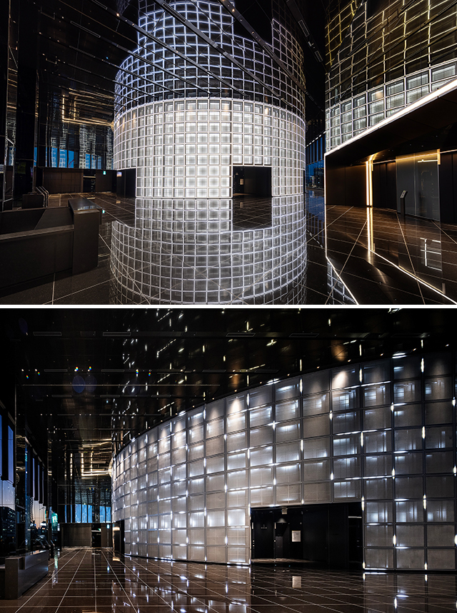
This guide follows the drawing-led route for custom stainless steel and other architectural metal packages. It covers the information baseline, panel schedules, sections, interfaces, field verification, finish approval, revision control and the first-piece check.
Treat the shop drawing as a release document
A shop drawing is more than a cleaned-up elevation. It is the link between design intent, a priced bill of material and the part that arrives at site. The drawing should state what is being made, how it is oriented, which revision is current and what still depends on a survey or another trade.
The older Metal Construction News guide on bent panels gives a practical baseline. It says the set should identify bends, quantities, lengths, trims and accessories, then move to architect and owner approval before the material list is released. It also calls for material descriptions and fastening or sealing information.
Start with a title block that names the project, area, drawing number, revision, issue purpose, author, checker and approval status. Add a short change description to every revision. A contractor should be able to tell in seconds whether the sheet is for coordination, approval, fabrication or installation.
Build the information baseline before detailing parts
Before a line is dimensioned, gather the inputs that can change the part: current backgrounds, substrate information, door and glazing schedules, service openings, finish references, quantity or BOQ, delivery sequence and survey status. If one input is missing, mark it as pending rather than hiding the gap inside a nominal dimension.
| Drawing sheet | What it should show | Approval question |
|---|---|---|
| General arrangement | Areas, datums, grid or room references, panel extents and interfaces | Does the metal package stop at the right boundary? |
| Panel or part schedule | Unique ID, quantity, material, finish, orientation, size and revision | Can the same ID be followed into fabrication and packing? |
| Plans, elevations and sections | Dimensions, joints, returns, reveals, carrier or fixing zone, access panels and adjacent construction | Can the installer locate the part without guessing? |
| Enlarged details | Corners, bases, heads, penetrations, movement gaps and transitions to glass, stone, timber or MEP | Is the interface buildable and maintainable? |
| Finish and inspection sheet | Approved sample reference, grain direction, viewing distance, protection and acceptance notes | Will the factory and site inspect the same visible condition? |
| Packing and installation map | Bundle or crate number, lifting orientation, sequence, spares and protection | Can the numbered parts reach the correct area intact? |
The schedule makes the set useful for procurement. Give folded panels, cassette modules and trims clear prefixes; a single “stainless panel” line is too broad to price or inspect.
Connect geometry to traceable fabrication data
Repeating modules can often be controlled with a good panel schedule and a typical section. Unique or curved geometry needs a stronger link between the model and the drawing. The United States Olympic Museum case described by Metal Construction News used a 3D master model for a facade with more than 8,500 unique diamond-shaped panels. The team created a 1:1 fabrication model for every panel and produced separate CNC, assembly and field-installation information. Each non-repeating part needs an identity and a checked source of geometry.
For a smaller project, controlled CAD or BIM may be enough. The panel ID, formed geometry, edge condition and installation location must stay aligned across files. When a design change moves a joint, update the elevation, section, schedule, fabrication file and packing map together, and remove superseded files from the release folder.
Kikukawa’s Shibuya Sakura Stage project gives a useful built example. Its overlapping escalators and elliptical atriums were coordinated with 3D modelling and detailed construction drawings. The same page describes a double-layer mesh screen with more than 650 one-metre panel units, most made accessible for inspection. A shop drawing should reserve the same attention for removable panels, inspection doors and service zones.

Resolve interfaces before the finish is frozen
Most late changes occur at the edge of a metal package. Confirm the datum and measure the substrate, openings, frames and finished floor or ceiling before the release that controls cutting and forming. Metal Construction News recommends measuring after the structure and relevant doors and windows are ready because built conditions can differ from design drawings. Record the survey date, reference points and inaccessible areas.
Show the interface with enough context to answer four questions:
- What supports the metal, and where can the carrier adjust?
- Where does water, air, movement or cleaning access go?
- Which trade owns the adjacent membrane, frame, glass, stone or service opening?
- Which part can be removed without damaging the approved finish?
The fixing route belongs in this detail, but it should not be detached from the panel build-up or access plan. A concealed clip, visible fastener, welded frame or bonded interface can each be valid in a selected system. The drawing must show the selected route, the datum, the movement direction and the installation sequence. It should not leave those decisions to a generic note.
Make finish approval measurable
Finish names such as brushed, mirror or PVD do not define the whole acceptance condition. Add a sample reference, viewing distance, lighting note, grain or pattern direction, protected face and edge treatment. For a large reflective panel, show the joint line and adjacent material in the sample or mock-up. A small coupon cannot prove a corner, a return, a service cut-out or a change in reflection across a full module.
The drawing should also state what the inspector can check before packing: panel ID, dimensions, edge closure, opening size, finish direction, protection film or paper and any required photo record. Avoid inventing a universal flatness or joint tolerance. Use the project specification, the selected system evidence and the approved first piece to set the acceptance limits.
Use a short, traceable approval workflow
An efficient workflow has distinct issue points:
- Coordination issue: the fabricator marks assumptions, missing inputs and interface questions.
- Design review: the architect, interior designer, facade consultant or contractor comments against a numbered revision.
- Field verification: the team confirms the substrate and openings that affect final dimensions.
- Fabrication release: the approved revision, schedule, detail set and manufacturing data are frozen together.
- First-piece check: a representative panel, edge, opening or corner is inspected before repetitive production.
Do not treat silence as approval. Record the approver, date, status and outstanding conditions. A comment that changes finish, panel break or service opening should trigger a revision and a check of connected sheets.
Connect Xinmao’s drawing route to the project package
Xinmao Metal’s stainless steel wall-panel collection is the relevant product path for flat, folded and cassette-style architectural panels. The advanced shop-drawing and value-engineering service provides the appropriate bridge from a concept detail to sections, schedules and a priced package. The 1:1 mock-up and prototyping service is useful when the design team needs to inspect a complete edge, joint, carrier and finish under project lighting.
The Shenzhen 50-storey office-building metal honeycomb cladding case is a relevant Xinmao reference for a multi-location package linking wall, column, elevator and exterior cladding with factory checking and installation coordination. It should be read as a project example, not as a universal detail or performance promise.
For an RFQ or drawing review, send the latest drawings, BOQ or quantity, material and finish reference, representative sections, access and service requirements, destination country and deadline. Xinmao’s contact page is the real route for that information.


A final pre-release checklist
Before fabrication, ask the team to confirm:
- every panel or assembly has one ID that appears on the elevation, schedule, detail, packing list and installation map;
- the latest survey status is visible and any assumed dimension is marked;
- material, grade, finish, face direction and protection reference an approved sample;
- edges, corners, joints, openings, movement gaps and adjacent trades have enlarged details;
- fixing, carrier, access and replacement logic are drawn as one assembly;
- the revision block records comments, approvers and the release purpose; and
- one representative module or 1:1 mock-up has a written acceptance record.
When should field measurements control the drawing?
When the substrate and the openings that govern the metal part are sufficiently complete to measure. Record the survey and update the affected sheets before fabrication release.
How much detail is enough?
Enough for the fabricator to make the part, the inspector to check it and the installer to locate it without a private interpretation. If an edge, interface or access panel still depends on a verbal explanation, the set is not ready.
Scope note: This article is a material, fabrication and specification guide. Final structural, wind, seismic, fire, drainage, corrosion, thermal, acoustic, accessibility and product-certification decisions remain with the appointed project professionals and the selected facade, cladding and metal contractors.