
A reflective stainless steel ceiling is not only a finish. It is a coordinated overhead system in which panel stiffness, suspension, service access, surface protection and replacement logic must agree before fabrication begins.
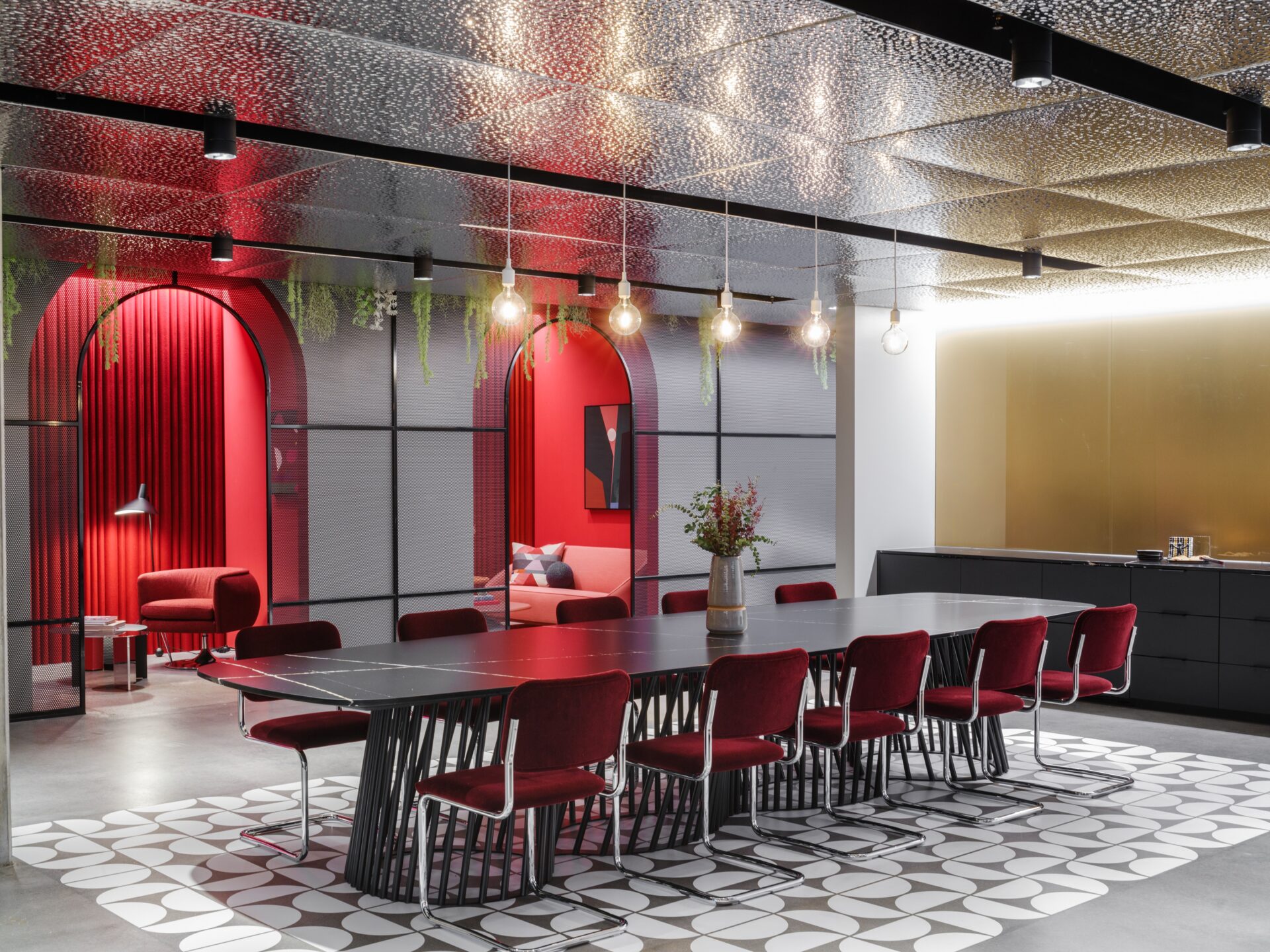
Ceilings are often released late, after the floor plan, lighting concept and mechanical layout have already moved through several revisions. That sequence is risky when the visible surface is reflective stainless steel. A small mismatch at a joint, a service hatch that does not align with the module, or a panel that flexes under its own weight can be more visible overhead than it would be on a wall.
A ceiling is an overhead system, not a sheet of finish
Interior stainless steel is attractive because it combines a controlled appearance with durability and a wide range of surface treatments. Outokumpu’s interior-cladding guidance places decorative architectural cladding alongside hygienic and high-use interior applications, and identifies cold-rolled coil, strip and sheet as versatile product forms. That is useful context, but it does not remove the need to define the actual ceiling assembly.
A ceiling package normally contains at least five interacting layers: the visible panel, its edge or return, the suspension or support interface, the accessible plenum and the services above it. Lighting, sprinklers, diffusers, sensors, speakers and inspection points add more constraints. If the module grid is fixed before those locations are coordinated, the metal fabricator inherits a geometry problem that should have been resolved in design.
Design principle: the reflected ceiling plan should be read together with the metal panel schedule, the access map and the MEP coordination model. A finish approval without those three documents is only a partial approval.
What the Mirror Ceiling case makes clear
Metal Architecture’s October 2025 case study describes a 169.3 m² workplace showroom ceiling designed by Gensler Architecture. The project used pebbled stainless panels in Rigidized Metals’ Pattern 1WND finish. The article records 1.6 mm panels, a width just under the material’s 1,219 mm maximum, and bends on all sides.
Those dimensions are project facts, not a universal specification. Their value is the engineering logic behind them. A flat, reflective panel can behave as a flexible membrane; the four-sided bends added integrity and allowed an accessible attachment to the Armstrong Heavy Duty Grid above. The fabrication team also used proximity-sensor laser cutters and non-marking press brakes to limit damage to the finished face.
Three lessons follow. First, panel stiffness can come from formed geometry rather than simply increasing sheet thickness. Second, material-width limits should influence module planning before the elevation is drawn as a continuous field. Third, finish protection has to be built into cutting, forming and handling—not added as a cleaning instruction after installation.
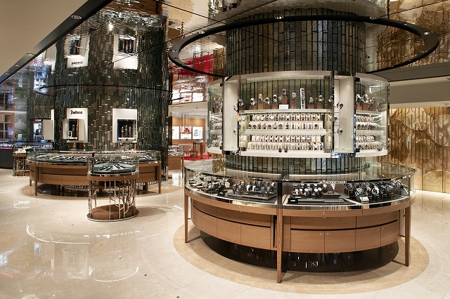
Module geometry is part of the structure
For a ceiling panel, the visible face and the edge return should be designed together. Return depth, corner relief, bend radius, hanger location and access direction influence deflection, alignment and the way light reads across the surface. A module that looks flat in elevation may need a folded perimeter, concealed stiffener or carefully spaced support points to remain visually stable in the room.
Before releasing fabrication drawings, confirm the maximum blank size, nesting direction, grain or pattern direction, bend sequence and the tolerance stack from the support grid to the finished face. A pebbled or embossed surface can mask small distortions in some lighting conditions, while a mirror-like area can exaggerate them. Patterned finishes may reduce the visual effect of oil-canning, but they do not replace a structural or tolerance check.
The BSSA finish guidance connects patterned and polished finishes with fabrication, installation, cleaning and maintenance care. The practical translation for a ceiling is to approve a sample that includes the return, corner and joint. A flat coupon cannot show how the surface will read after forming or how an access panel will align with neighbouring modules.
Access and MEP coordination should happen before the grid is frozen
Accessibility is not a secondary convenience on an interior ceiling. Service engineers may need to reach valves, dampers, filters, controls or junctions after handover. If the only available panel is a large, heavy or visibly different piece, future maintenance can damage adjacent finishes or interrupt the design intent.
A useful access map identifies every panel that can be removed, the direction of removal, the clearance required below and the service that it serves. It should also show whether the panel needs a concealed latch, a removable clip, a two-person lift, a temporary protection board or a separate replacement part. The access decision can affect module size and edge geometry as much as the lighting layout does.
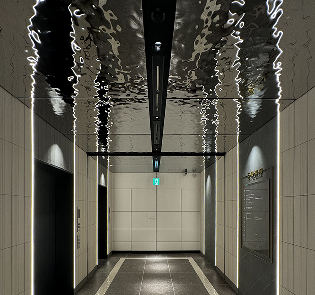
Overhead support also deserves an explicit load path. In the ASSDA report on Narre Warren Station, the ceiling support concept was re-engineered around stainless cable bow-string trusses. The case records 25 m spans, 316 stainless cable and fittings, modular installation, load analysis, geometry modelling, testing and QA/QC. It is not a template for a decorative ceiling, but it demonstrates the benefit of resolving the overhead support path and installation sequence before work reaches a constrained site.

Surface finish, forming and protection are one sequence
A reflective or textured stainless surface is vulnerable at predictable moments: nesting and cutting, press-brake contact, stacking, transport, lifting, temporary fixing, sealant work and final cleaning. The protection plan should name the contact materials, protective film or interleaving method, removal timing and inspection points. “Protect during installation” is too vague for a ceiling that will be viewed against light.
The ASSDA Stainless Steel Specialist Course treats material properties, finish, fabrication, forming, design, corrosion and selection as connected subjects. That sequence is appropriate for ceiling work. The material schedule should state the grade family and thickness only after the interior environment, cleaning regime, exposure and forming requirements are understood. Stainless steel should not be written as 304 or 316 by default.
KIKUKAWA’s Minamo Panel page is a helpful case-specific reminder: it identifies SUS304, 1.0 or 1.5 mm sheet, a mirror finish and a textured embossed surface for interior applications. Those values belong to that product and project context. They should not be copied into another ceiling without checking support spacing, surface process, fire requirements, access loads, cleaning chemicals and the supplier’s forming limits.

Specification and fabrication considerations
| Decision | Record in the package | Risk controlled |
|---|---|---|
| Module geometry | Blank size, return depth, corner relief, bend radius, pattern direction and tolerances | Flexing, misalignment, visible pattern breaks and rework |
| Support interface | Grid or subframe, hanger points, load path, attachment method and movement allowance | Deflection, rattle, inaccessible fixings and unsafe installation |
| Access / MEP | Removable panels, clearance, latch or clip logic, service ownership and replacement sequence | Damaged finishes and future maintenance that cannot be performed |
| Finish control | Approved sample with return and joint, surface direction, handling protection and cleaning method | Scratches, inconsistent reflection, contamination and late cleaning damage |
| Fabrication evidence | Cutting and forming method, non-marking contact controls, inspection points and packaging | Press-brake marks, distortion and untraceable surface defects |
| Handover | As-built panel map, spare/replacement reference, access instructions and maintenance record | A ceiling that looks complete but cannot be maintained |
Architects and contractors should consider
- Freeze the ceiling module only after the reflected ceiling plan, MEP access map and support layout have been reviewed together.
- Approve the real folded sample. Include the perimeter return, corner, joint, access panel and the lighting condition that will reveal the finish.
- Separate visible-panel criteria from suspension and service criteria, but keep both in one coordinated drawing package. A supplier’s decorative sample cannot prove the load path.
- Check material width, nesting, lifting and storage before selecting a large continuous field. The largest-looking panel is not automatically the most economical or maintainable.
- Define how an access panel is removed without dragging tools, ladders or protective boards across the visible surface.
- Do not transfer a project-specific grade, thickness, finish or fire/acoustic claim to another building without rechecking the environment and the applicable approvals.
When the ceiling is released as a coordinated package
For Xinmao Metal, the useful industry judgement is that an architectural ceiling should be released as a metal package, not as a finish board. The package should connect the approved surface to the panel blank, folded geometry, support interface, access map, tolerance strategy, protection method and replacement part.
That judgement is naturally connected to Xinmao’s Advanced Shop Drawing & Value Engineering: module dimensions, grid interfaces, service openings and fabrication limits should be visible before production. A 1:1 Mock-Up & Prototyping review can test reflection, panel joints, access and handling. The relevant product association is Xinmao’s architectural stainless steel ceiling collection, while the material decision should remain project-specific rather than a promise of an automatic grade, finish or performance rating.
Where the ceiling is exposed to moisture, aggressive cleaning or unusual service conditions, Climate-Resilient Material Solutions is a relevant planning reference. The point is not to turn a content article into an advertisement; it is to show how a design idea becomes a traceable engineering conversation about material, fabrication and maintenance.
Conclusion
Reflective stainless steel ceilings reward precise coordination and expose casual coordination. The strongest examples treat panel stiffness, sheet width, suspension, access, MEP interfaces and finish protection as one design problem. They also keep project-specific facts separate from general specification rules.
For a durable result, approve more than a colour or texture. Approve the formed panel, the support path, the access method, the protection sequence and the replacement logic. When those decisions describe the same assembly, a stainless steel ceiling can remain visually controlled from first installation through future maintenance.
Sources
- Metal Architecture — Mirror Ceiling Brings Reflective Drama to Workplace Showroom
- ASSDA — From 30 tonnes of carbon steel to 3 tonnes of stainless cable
- Outokumpu — Stainless steel for interior cladding
- ASSDA — Stainless Steel Specialist Course brochure
- BSSA — Do’s and Don’ts in Selecting and Specifying Stainless Steel Surface Finishes
- KIKUKAWA — Minamo Panel