
The edge of a facade is where appearance, water, movement and maintenance meet. A stainless steel coping or flashing only performs when the visible trim and the concealed envelope layers are designed as one system.
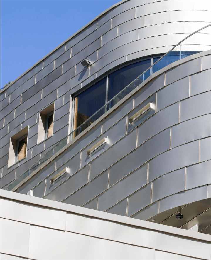
At roof lines, parapets, sills, bases and penetrations, slope and clearance determine whether water leaves the assembly or enters it. Stainless steel is often chosen for these exposed parts because it can provide a durable, visually controlled surface. That choice does not remove the need for a drainage cavity, a water-control layer, compatible interfaces, movement allowance and a maintainable joint.
The edge is a boundary between control layers
The American Institute of Architects’ building-performance definitions describe a rainscreen wall as an exterior cladding, a cavity and an inner water-control layer. The cavity is not empty space: it collects and directs water that passes the outer layer, while ventilation helps remove residual moisture. Metal Architecture’s “Four Ds” framework expresses the same practical sequence as deflection, drainage, drying and durability.
This distinction matters at a stainless steel edge. A coping may shed rain from the top of a parapet, but the wall behind still needs a complete water-control strategy. A sill needs a positive drip and an outlet; a base trim needs a path that does not discharge onto a vulnerable finish; a roof penetration needs a back-flashing arrangement that deals with the catchment above it. The stainless part is the visible weathering component, not the entire waterproofing system.

The first drawing review should follow the water route from high point to discharge. Ask where water enters, where it is collected, how it is turned outward, how the cavity dries, and what prevents the edge from trapping debris. If those questions are answered by a sealant note, the detail is carrying too much risk in one consumable joint.
Give water a defined route at every transition
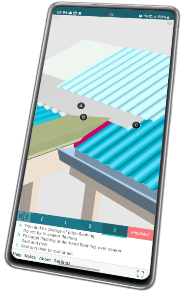
The current NZ Metal Roofing Manufacturers Code of Practice treats flashing as part of the roof-cladding system, not as a decorative afterthought. It distinguishes transverse and longitudinal flashings, discusses pressure equalisation behind outer edges, and warns that a sealed lap secured with fasteners can behave as one longer piece for movement purposes. It also requires material compatibility to be considered rather than assumed.
For architectural stainless steel, the design implications are straightforward:
- Coping and parapet caps: provide a positive fall, a controlled drip, and a joint that can move without opening a path into the wall.
- Sills and base flashings: keep the discharge away from the face below; do not let a horizontal return create a dirt shelf or a capillary bridge.
- Roof penetrations: select the flashing geometry by roof position, catchment area and debris exposure. The NZMRM reference distinguishes over-flashing, under-soakers, hidden gutters and cricket arrangements rather than treating every penetration alike.
- Rainscreen edges: maintain the cavity’s drainage and ventilation openings. Do not close the cavity with a trim that looks tidy but blocks the exit route.
The Nickel Institute roofing, flashing and coping guide adds an important material check: grade selection depends on the fluid and exposure. Soil contact, coastal conditions and de-icing salt can require more corrosion-resistant stainless steel than a dry, sheltered location. This is not a reason to specify 316 by reflex. It is a reason to document the exposure, the runoff path and the maintenance expectation before the grade is fixed.
Movement, joints and replacement are part of durability
Stainless steel trims still expand, contract and deflect. The NZMRM guidance notes that production length, profile strength, fixing pattern and local climate affect where expansion provisions are needed. It also warns against wet contact between flashing edges and concrete, plaster or butyl rubber, and against abrasion at cut edges. These interface details belong in the drawing, not in site improvisation.
An edge package should show:
- the fixed point and the sliding point;
- joint width and movement direction;
- the cleat, clip, fastener and isolator;
- the water path at the joint; and
- how a damaged section can be removed without dismantling half the facade.
The last point is often missed. A hidden flashing that cannot be reached may need a service life comparable with the cladding because replacement would require progressive dismantling. A removable counterflashing or two-piece parapet joint may be visually quieter than a continuous welded line and easier to inspect when the membrane or sealant eventually needs attention.
The December 2025 NYCHA roof-specialties specification illustrates the level of coordination a specific project may demand. It requires shop drawing approval before fabrication, calls for prefabricated one-piece corners with soldered or welded seams, and lists stainless fascia, sumps, copings, leaders and counterflashings. Its requirements are project-specific, not universal rules, but they make the approval logic visible: roof-edge profiles, materials, corners, wind resistance, joints and installation responsibility belong in one reviewed package.
Material, finish and fabrication decisions at the edge
Stainless steel is a family of materials, and an edge trim sees a different environment from a sheltered interior panel. Chlorides, polluted runoff, condensation, dissimilar-metal contact, cleaning chemicals and trapped construction residue can all change the result. A material schedule should therefore identify the grade family, thickness, surface finish, support metal, isolator, joint method and cleaning expectation without inventing a universal grade.
Finish direction is also an engineering and maintenance decision. ASSDA’s No. 4 finish guidance notes that line direction can affect drainage and corrosion behaviour; it is not enough to write “brushed stainless” when a long coping or sill will be read in reflected light. The approved sample should include the folded edge, return, corner and joint—not only a flat sheet.
The Silvretta Therme case from Outokumpu is useful as a project example because the facade and soffit package combines a defined surface finish, forming process, material thickness and a named grade. Its 304/4301, DURA-Matte Champagne finish, 0.5 mm thickness and 7,500 m² project data belong to that case and are not a recommendation for every roof edge. The lesson is the coordination sequence: visual intent, surface process and formed panel behaviour were considered together.
Specification and fabrication checkpoint
| Decision | Include in the package | Failure avoided |
|---|---|---|
| Water route | Falls, drips, overlaps, cavity openings, outlets and discharge location | Ponding, staining and uncontrolled water behind the edge |
| Movement | Fixed/sliding points, joint width, clearances and thermal assumptions | Buckling, noise, torn sealants and open laps |
| Compatibility | Adjacent metals, membranes, concrete/plaster contact, isolators and sealants | Galvanic corrosion, abrasion and premature interface failure |
| Fabrication | Fold radii, corner method, weld/solder treatment, finish direction and tolerances | Distortion, inconsistent appearance and site rework |
| Maintenance | Inspection route, removable part, cleaning method and replacement sequence | An inaccessible primary weathering component |
| Approval evidence | Sample, shop drawing revision, material record, mock-up and test responsibility | A visual approval that does not match the buildable assembly |
Architects and contractors should consider
- Start with the envelope section, not the cap profile. Show the outer trim, cavity, water-control layer, insulation, substrate and interior finish together.
- Keep roof and facade responsibilities aligned. The membrane contractor, metal fabricator, facade contractor and waterproofing designer should review the same edge detail.
- Treat corners and penetrations as design areas. Prefabrication can improve control, but only if the corner geometry, joint and installation tolerances are resolved before production.
- Do not use sealant as a substitute for a fall, drip, overlap or cavity outlet. Sealant has a maintenance life; the drainage logic should remain intelligible when it is replaced.
- Approve the actual surface orientation. A brushed line that looks consistent on a flat sample may read differently after folding, turning a corner or receiving runoff.
- Record what is project-specific. A public specification may call for a particular gauge, grade, wind test or installer arrangement; transfer the decision only when the project conditions support it.
When the edge becomes a package
Xinmao Metal’s useful industry judgement is that a rainscreen edge should be released as a coordinated metal package, not purchased as a trim profile. The package should connect the approved surface to the folded section, cleat, bracket, fastener, isolator, membrane termination, cavity opening, movement joint, discharge route and replacement method.
That approach aligns with the information expected from Advanced Shop Drawing & Value Engineering. Exposure and water management should remain visible through Climate-Resilient Material Solutions, while a 1:1 Mock-Up & Prototyping review can test the finish, corner, drip, membrane interface and installation sequence before volume fabrication. The connection to Xinmao’s architectural scope is a coordination judgement, not a claim of a named roof-edge project or a universal tested system.
Conclusion
Long-life stainless steel facades are decided at their least photogenic locations: parapet caps, sills, bases, penetrations, laps and access points. A durable surface cannot compensate for a blocked cavity, missing drip, incompatible support or a joint that cannot move.
The strongest specification makes the water route and maintenance route as clear as the elevation. When coping, flashing, drainage, movement, finish, fabrication and replacement are reviewed as one assembly, stainless steel can contribute to a facade that is both visually controlled and materially honest.